🔗Getting started
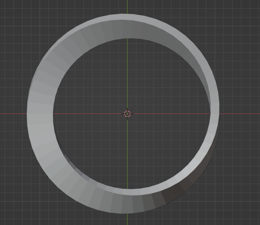
First I'll describe the steps needed to make a 3d mobius strip then we'll implement those steps in Python code.
If you aren't familiar with using Python in Blender I'd recommend reading my article on Setting up Blender. It is written for Linux, but the section Importing local Python files applies to all operating systems and will help make it easier to run Python code.
🔗General Overview
We will loop over a specified resolution, creating 4 vertices at each iteration, and then apply some transformations to move and rotate them into the correct positions. This will create all of the vertices needed for the mesh. I will not demonstrate creating edges or faces here and leave that for the code; the most important part here is understanding the steps taken to make the general shape.
🔗Axes

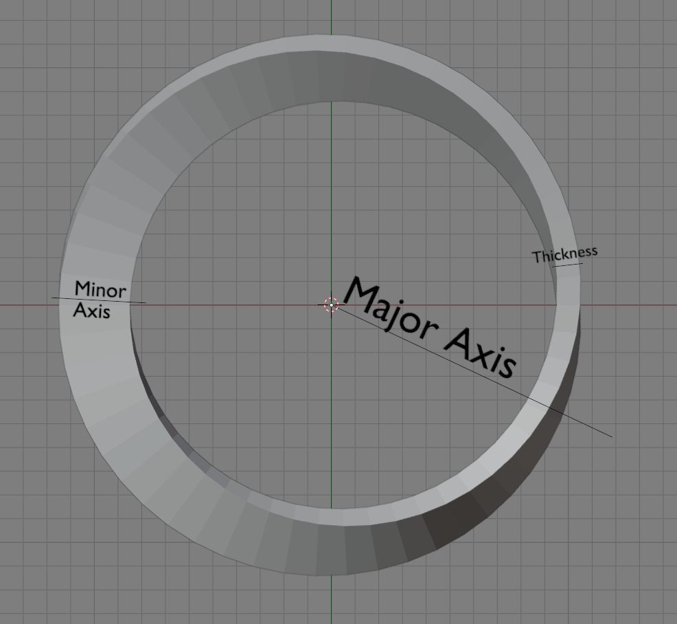
Note: we will be using the y axis in Blender as the minor axis and z as the major axis, rotations will be applied around these axes (like rotating around a cylinder or a pole).
🔗Steps
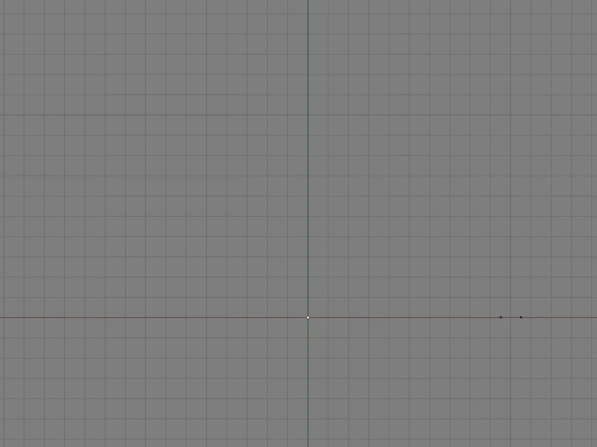
- Create 4 vertices. The width between the vertices is the
thickness(distance between front and back sides) and the height is theminor_radius(how tall it should be).Front view

The vertices form a rectangle - Rotate those vertices around the minor axis
Front view

Rotate around minor axis - Move the vertices
major_radiusunits away from the centerFront view

Move vertices away from the center - Rotate the vertices around the major axis
Top view

Rotate around major axis
Here are the vertices after each loop iteration:
Top view

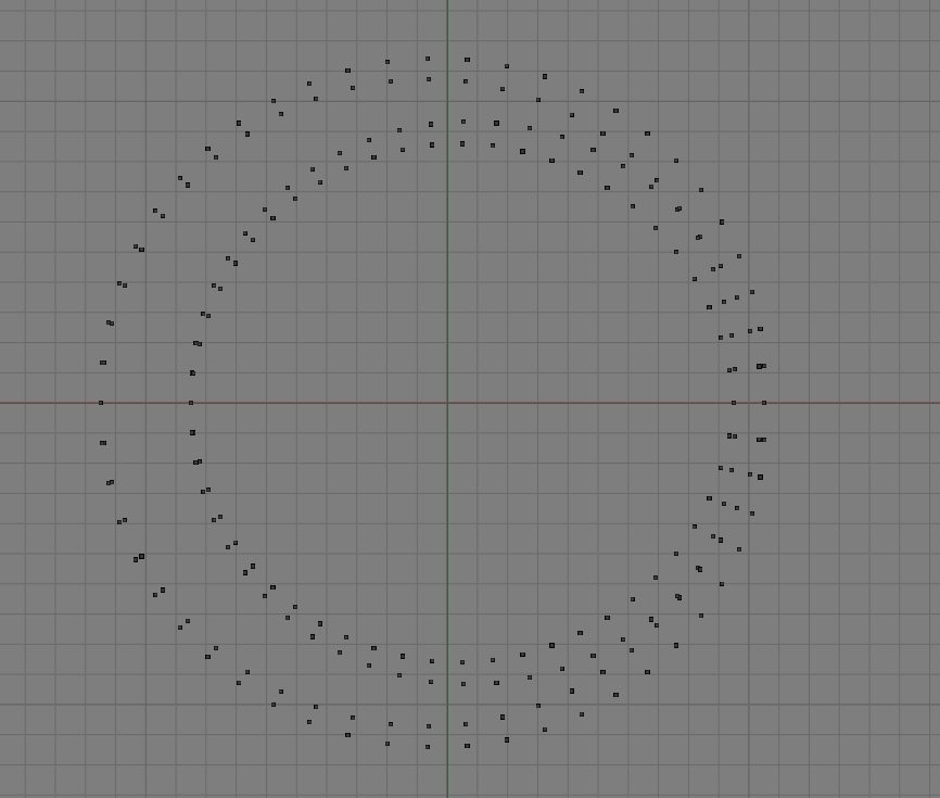
Then we just repeat this for the rest of the loop and we will have placed all of our vertices.
Top view

🔗Python Code
We will be using Blender's Mathutils module - specifically the Vector and Matrix types. Vector will be used to store 3d coordinates and Matrix will be used to rotate the coordinates.
Note: just like above we will be using the y axis as our minor axis, and z as our major axis.
🔗Imports
Let's import some math libraries and Blender's Python utilities:
import bpy
from math import *
from mathutils import Vector, Matrix
🔗Helpers
Let's define an apply function to multiply a 3d coordinate (vector) with a matrix in order to rotate it:
def apply(matrix, vector):
    '''
    apply(matrix, vector) -> vector

    this function receives a matrix and a vector and returns
    the vector obtained by multipling each row of the matrix
    with the vector
    '''
    V_0 = vector @ matrix[0]
    V_1 = vector @ matrix[1]
    V_2 = vector @ matrix[2]
    return Vector((V_0, V_1, V_2))
We'll talk more about matrices later.
🔗Variables
We'll create a function with some user-defined variables:
def mobius(major_radius: float = 1, minor_radius: float = 0.15, thick: float = 0.1, resolution: int = 108):
    '''
    major_radius - how large the strip will be
    minor_radius - defines how tall the strip will be (surface width)
    thick        - distance between front and back sides
    resolution   - number of loop iterations to perform
    '''
Initalize an empty list to hold our vertices and eventually faces:
verts = []
faces = []
And finally create a variable that represents the distance to move the vertices away from the center, which will be used later (shown in step 3 from earlier):
dx = Vector([major_radius, 0, 0])
When added to another vector this will move the vertices major_radius units away from the center, which will be applied before rotating around the major axis. We store the distance in the x coordinate to move vertices horizontally before rotating around the z axis (in step 4).
🔗Adding vertices
Let's define our main loop:
for i in range(resolution):
    # the angle to rotate around the minor axis (covers a 180° rotation)
    phi = pi * i / resolution

    # the angle to rotate around the major axis (covers a 360° rotation)
    theta = phi * 2

    # how many vertices do we have in our list
    idx = len(verts)
In the loop body we define two angles, represented in Radians. The angles will be gradually increased as i is incremented.
phi represents the angle to rotate around the minor axis (step 2 from earlier). It will end up covering a 180° rotation, which means it will only be rotated half way. This is how we rotate the surface of the mobius strip. The vertices of the last loop iteration will rotated 180° so the top of those vertices will connect to the bottom of the vertices from the first loop iteration and vice versa.
theta represents the angle to rotate around the major axis (step 3 from earlier). It will end up covering a 360° rotation, which means it will be rotated all the way around. This is how we get an overall circular shape.
idx is our current position in the list of vertices. We will use this later to create faces between the vertices.
🔗Initial vertices
In the body of the loop we'll create our initial points (step 1 from earlier):
p0 = Vector(( -thick/2, 0,  minor_radius ))
p1 = Vector((  thick/2, 0,  minor_radius ))
p2 = Vector((  thick/2, 0, -minor_radius ))
p3 = Vector(( -thick/2, 0, -minor_radius ))
Since the four vertices will initially be a rectangle be centered around (0, 0), we can just specify the coordinates we want. The thickness is divided by 2 because thick defines the total thickness, not the distance from the center (although that detail is less important since we could have just defined thick = 0.05 instead of using 0.1).
🔗Defining Rotation Matrices
In order to create the mesh we'll need to use a little math. If you're not familiar with rotation matrices that's ok, the most important thing to know is that we can multiply a vector (which stores the (x,y,z coordinates) by a matrix in order to rotate the coordinates. For more detailed information on how this works see Wikipedia - Rotation matrix or Stack Exchange - Understanding rotation matrices.
Here we create a couple rotation matrices to rotate our vertices around the major and minor axes:
# Rotates along major radius
# angle=theta, size=3, axis=[0, 0, 1]
rot_theta = Matrix.Rotation(theta, 3, [0, 0, 1])

# Rotates along minor radius
# angle=phi, size=3, axis=[0, 1, 0]
rot_phi = Matrix.Rotation(phi, 3, [0, 1, 0])
rot_theta uses [0, 0, 1] to specify a rotation around the z axis while rot_phi uses [0, 1, 0] to specify a rotation around the y axis. The size is set to 3 because we want a 3-dimensional matrix.
🔗Transforms
We will need to perform three operations on the vertices:
-
Rotate around the minor axis (as seen in step 2)
p0_rotated = apply(rot_phi, p0)
p1_rotated = apply(rot_phi, p1)
p2_rotated = apply(rot_phi, p2)
p3_rotated = apply(rot_phi, p3)
We are using the
apply()function from earlier to multiply each row of the rotation matrix by the 3d coordinates in the vector: -
Move the vertices away from the center (horizontally, as seen in step 3)
p0_moved = p0_rotated + dx p1_moved = p1_rotated + dx p2_moved = p2_rotated + dx p3_moved = p3_rotated + dx -
Rotate around the major axis to get our final vertices (as seen in step 4)
v0 =  apply(rot_theta, p0_moved)
v1 =  apply(rot_theta, p1_moved)
v2 =  apply(rot_theta, p2_moved)
v3 =  apply(rot_theta, p3_moved)
Then we will add those vertices to our list of vertices with:
verts.extend([v0, v1, v2, v3])
🔗Faces
Faces are added by connecting multiple vertices. Each vertice is referenced by its position in the verts list.
-
First we identify the next vertices that will be added, assuming we are not at the end:
# `idx` represents the position of the first newly added vertice # so since we want the position of the next vertices we add 4 to that next_verts = idx + 4 # If we are not at the end of the loop we find the index positions # of the next vertices in the `verts` list if i+1 < resolution: n0 = next_verts + 0 n1 = next_verts + 1 n2 = next_verts + 2 n3 = next_verts + 3 -
If we are at the end we handle that differently:
# Otherwise reference the vertices created the very first loop iteration
else:
    n0 =  2
    n1 =  3
    n2 =  0
    n3 =  1
Remember the top and bottoms get switched at the end because it will be rotated by 180°, so the vertices do not have an obviousordering.
-
And finally let's create those faces in our list:
faces.append([idx+0, idx+1, n1, n0])  # top face
faces.append([idx+1, idx+2, n2, n1])  # front side face
faces.append([idx+2, idx+3, n3, n2])  # bottom face
faces.append([idx+3, idx+0, n0, n3])  # back side face
Remember
idxis the position of the first newly added vertice in the list
🔗Adding the mesh
Once the loop is finished we can use the verts and faces lists to create our mesh using from_pydata() and validate using validate() (which returns true if the mesh is invalid).
# Create a blank mesh
mesh = bpy.data.meshes.new("mobius_strip")

# Create a mesh from the given vertices and faces
mesh.from_pydata(verts, [], faces)

# Ensure the mesh is valid
if mesh.validate():
    print('Invalid mesh')
    return

# Create a new object
ob = bpy.data.objects.new("Mobius Strip Mesh", mesh)

# Add our object to the current collection
bpy.context.collection.objects.link(ob)

🔗Final code
Here is the code:
import bpy
from math import *
from mathutils import Vector, Matrix

def apply(matrix, vector):
    '''
    apply(matrix, vector) -> vector

    this function receives a matrix and a vector and returns
    the vector obtained by multipling each row of the matrix
    with the vector
    '''
    V_0 = vector @ matrix[0]
    V_1 = vector @ matrix[1]
    V_2 = vector @ matrix[2]
    return Vector((V_0, V_1, V_2))

def mobius(major_radius: float = 1, minor_radius: float = 0.15, thick: float = 0.1, resolution: int = 108):
    '''
    major_radius - how large the strip will be
    minor_radius - defines how tall the strip will be (surface width)
    thick        - distance between front and back sides
    resolution   - number of loop iterations to perform
    '''

    verts = []
    faces = []
    dx = Vector([major_radius, 0, 0])

    for i in range(resolution):
        # the angle to rotate around the minor axis (covers a 180° rotation)
        phi = pi * i / resolution

        # the angle to rotate around the major axis (covers a 360° rotation)
        theta = phi * 2

        # how many vertices do we have in our list
        idx = len(verts)

        p0 = Vector(( -thick/2, 0,  minor_radius ))
        p1 = Vector((  thick/2, 0,  minor_radius ))
        p2 = Vector((  thick/2, 0, -minor_radius ))
        p3 = Vector(( -thick/2, 0, -minor_radius ))

        # Rotates along major radius
        # angle=theta, size=3, axis=[0, 0, 1]
        rot_theta = Matrix.Rotation(theta, 3, [0, 0, 1])

        # Rotates along minor radius
        # angle=phi, size=3, axis=[0, 1, 0]
        rot_phi = Matrix.Rotation(phi, 3, [0, 1, 0])

        p0_rotated = apply(rot_phi, p0)
        p1_rotated = apply(rot_phi, p1)
        p2_rotated = apply(rot_phi, p2)
        p3_rotated = apply(rot_phi, p3)

        p0_moved = p0_rotated + dx
        p1_moved = p1_rotated + dx
        p2_moved = p2_rotated + dx
        p3_moved = p3_rotated + dx

        v0 =  apply(rot_theta, p0_moved)
        v1 =  apply(rot_theta, p1_moved)
        v2 =  apply(rot_theta, p2_moved)
        v3 =  apply(rot_theta, p3_moved)

        verts.extend([v0, v1, v2, v3])

        # `idx` represents the position of the first newly added vertice
        # so since we want the position of the next vertices we add 4 to that
        next_verts = idx + 4

        # If we are not at the end of the loop we find the index positions
        # of the next vertices in the `verts` list
        if i+1 < resolution:
            n0 = next_verts + 0
            n1 = next_verts + 1
            n2 = next_verts + 2
            n3 = next_verts + 3
        # Otherwise reference the vertices created the very first loop iteration
        else:
            n0 =  2
            n1 =  3
            n2 =  0
            n3 =  1
        faces.append([idx+0, idx+1, n1, n0])  # top face
        faces.append([idx+1, idx+2, n2, n1])  # front side face
        faces.append([idx+2, idx+3, n3, n2])  # bottom face
        faces.append([idx+3, idx+0, n0, n3])  # back side face

    # Create a blank mesh
    mesh = bpy.data.meshes.new("mobius_strip")

    # Create a mesh from the given vertices and faces
    mesh.from_pydata(verts, [], faces)

    # Ensure the mesh is valid
    if mesh.validate():
        print('Invalid mesh')
        return

    # Create a new object
    ob = bpy.data.objects.new("Mobius Strip Mesh", mesh)

    # Add our object to the current collection
    bpy.context.collection.objects.link(ob)

# run the function
mobius()
You can just paste that code into new a Blender text document and press the Run icon (the triangle) and a 3d mobius strip will appear!
🔗Download
Or you can download the final code here: mobius_strip.py
🔗Credits
This article is basically a much more verbose explanation and reimplementation of the code from this Stack Exchange post